Understanding The Critical Focus Zone Of A Fast Apochromatic Lens
By
Steve Luce
Introduction
I have been studying focus and optical alignment of fast apochromatic telescopes for several years. I am extremely impressed with the quality of modern optics but I have come to believe that focus and alignment are as important as the optics themselves. The best of apochromatic of lenses can be reduced to a substandard lens with poor focus or collimation.
I also wanted to understand the role of my Rigel Systems stepper motor in the precision focus process.
This article is a detailed documentation of focus tests and refractor optics as they apply to wide field astrophotography.
Equipment
An APM 105/650, f/6.2 LZOS triplet scope was used
in these tests. The APM scope uses the same optics as the
For a camera, I used a modified Canon 20D. The Canon has a 15 mm x 23 mm CCD and requires a flat field circle 28 millimeters in diameter.
APM recommends that some kind of field flattener be placed in the optical path for wide field astrophotography. This means that any image taken with an uncorrected APM scope using a Canon 20D or similar large CCD will be in focus for most, but not all, of the image. The areas not in focus will be at the extreme four corners of the CCD frame.
Tele Vue recommends the .85x flattener/reducer for scopes up to 600 mm. I must make the point that the Tele Vue flattener specification is out of range for a 650 mm scope. The resulting, partially flattened, field is typical of optics in astrophotography and helps to demonstrate complex focus issues facing today’s astrophotographer.
The tests that I include in this article show that the Tele Vue produces surprisingly good results even at 650 mm and that the Rigel Systems stepper motor focus systems used on the scope does a supreme job of finding the best possible position of the CCD plane within the focus zone for the triplet.
I used a Losmandy G11/Gemini mount and guide system. The guide camera CCD is made by Orion and the guiding accuracy of the drive during these tests was held to less than one pixel of error.
The point of this test documentation was focus and not image quality. Image development was minimal and done in Photoshop specifically to compare focus change from image to image. Focus was adjusted with the Rigel Systems stepper motor control system. The stepper motor was fitted to the standard Starlight two-inch Feather Touch focuser, standard on the APM scope.
.
Astrophotography Setup
I picked a convenient area of the sky with a single bright star for quick focus of the camera, and alignment of the guide system. Once the scope was tracking, I was able to take a series of photos to test the flattener and stepper motor focus system.
The exposure times were less than 30 seconds to
reduce star bloat from atmospheric changes and guide corrections. The
temperature during the tests was 55 degrees Fahrenheit and did not
change more than 2 degrees over the entire test. Thermal changes to the
scope and focuser were minimal.
The Initial
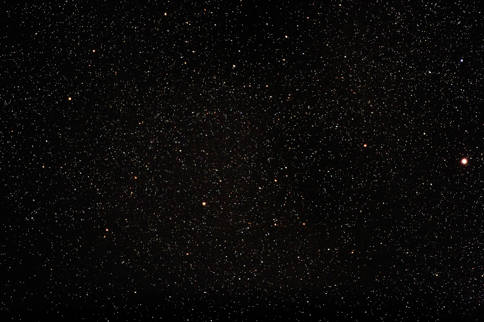
Full Frame Image
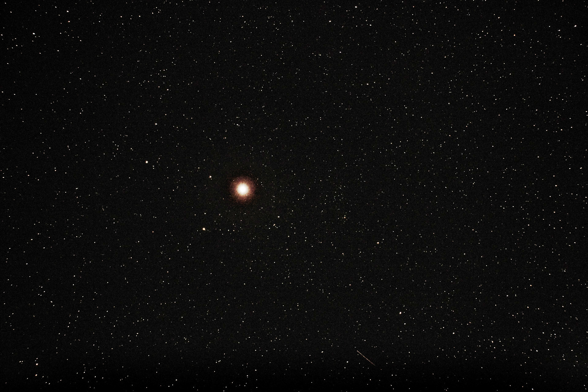 |
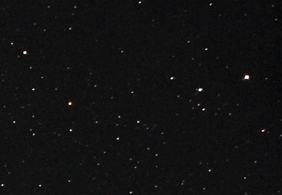
| Figure 1 - Initial full frame image at rough focus (Image 2083) |
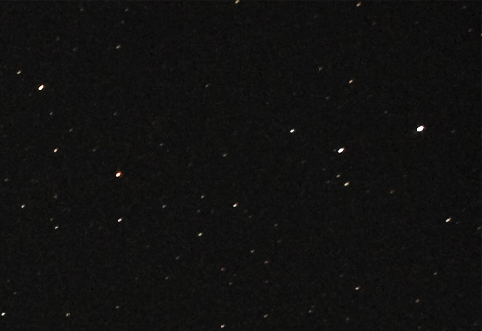
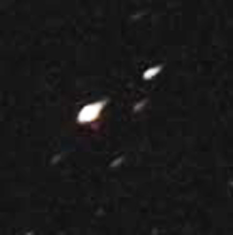
Figure 2 - Upper right corner of the
initial image (image 2083)
At first glance, the image in Fig. 1 looks good. However, Fig. 2 is a sample from the upper right corner and shows typical field curvature, corner star distortion.
Because the corners were out of focus (distorted), I picked a corner area to examine focus changes from image to image.
I moved the CCD toward the objective 25 microns per step to document the change in the corner star distortion as focus improved. Image 2083 in Fig. 2, was the first image of the set.
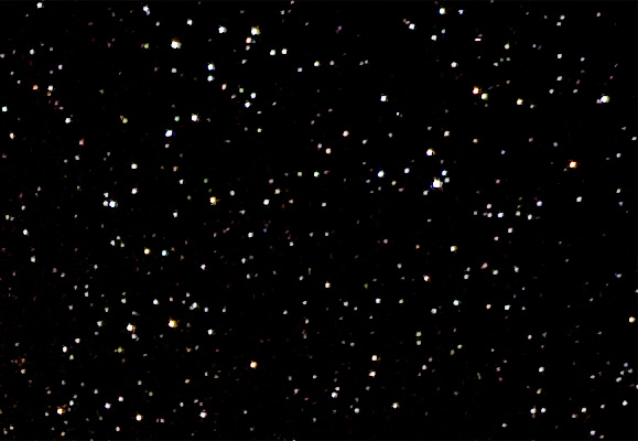
A Map Of
This Study
The red box sample area in Fig. 3 is 580 x 400 pixels. I took the same sample from the same place on each image in this test series. The image numbers are 2083 through 2112 for this focus study. The 580 x 400 images are at 100%. The numbers are the camera counter numbers. I also looked at a 200% star detail in the corner (green box) and the center (blue box) of each image.
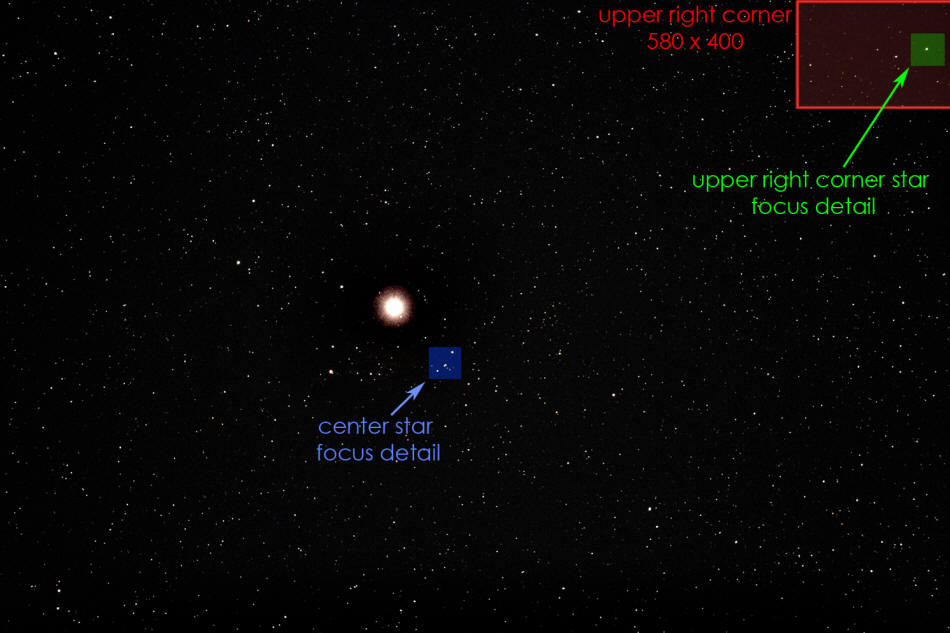 |
| Figure 3 - A map of this focus study (image 2083) |
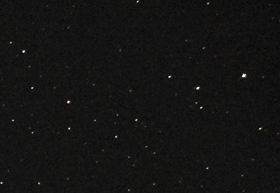 |
| Figure 4 - upper right corner of image 2106 (about 565 microns from 2083) |
Image 2106 is about 565 microns closer to the objective than image 2083 in Fig. 2.
As corner focus improves, the egg shape shortens.
 |
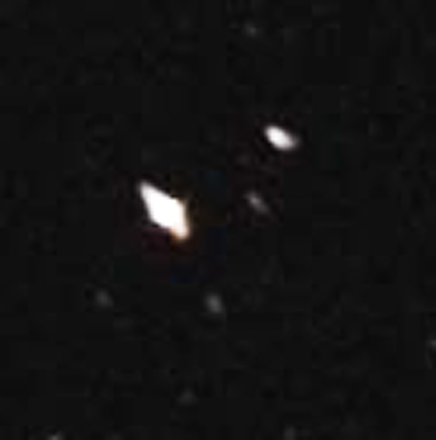
| Figure 5 - Upper right corner of image 2112 (about 70 microns from fig. 4) |
Image 2112 in Fig. 5 is a sample of corner focus that is about the best this optical system can do.
The focuser change from 2106 to 2112 is about 70 microns.
This corner star optical
distortion transition point is an excellent place to check collimation.
By examining an image in all four corners, collimation can be checked by
comparing the star distortion pattern in each corner. If all four
corners are similar in appearance (or identical as with the APM),
regardless of distortion amounts, the objective is well aligned and the
CCD and objective are parallel to each other. This test is very
sensitive.
More Detail On Corner Star Distortion
As the CCD is moved closer to the objective, the corner star distortion changes from Fig. 6 to Fig. 7 in shape. If the flattener is well designed and compatible with the objective, there will be a zone where the corner stars are round.
 |
| Figure 6 - Too far |
 |
|
| Figure 7 - Too close | |
Fig. 6 is a corner star out of focus where the CCD is too far from the objective.
Fig. 7 is a corner star out of focus where the CCD is too close to the objective
Fig.
8.
8 is star detail showing the changing distortion in the corners.
These are 200% images. A rough focus change of 25 microns change per
image was used from 2083 to 2108. A fine focus of 5 microns change per
image was used for images 2008 through 2012.
If you look carefully at the upper star detail, you
can see the star shape changing from the
Fig. 6 distortion to a four
point distortion.
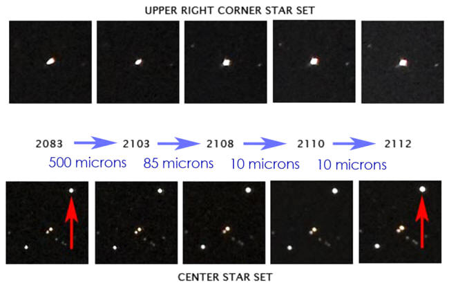
Figure 8 -
Corner star and center star focus changes as the CCD moves
toward objective
The images in Fig. 8 are an unfortunate example of a crossover without ever producing a good corner star shape.
This is a corner star on its way to the distortion seen Fig. 7. The star is morphing from the Fig. 6 shape to the Fig. 7 shape without ever being a true round star. If the flattener were perfect in this area of the image, 2112 would be circular with no flares. This is a form of astigmatism and a common optical problem for the amateur astrophotographer.
It is also important to realize that these changes are a result of a 20 micron linear change of the focuser. Twenty pound paper is 100 microns thick.
Please remember that the Tele Vue flattener/reducer is performing beyond the manufacturer specs. This error is not the fault of the triplet or the flattener. The combination of the APM objective and the TV flattener are simply beyond their specified ranges for full frame focus.
A Problem With The Center Star Focus As The Corners Stars Are Focused!
If you look closely at Fig. 8 you can see an unpleasant surprise. The lower set of star photos are from the center of the image. The red arrows show the center star focus getting worse as the corner stars get better.
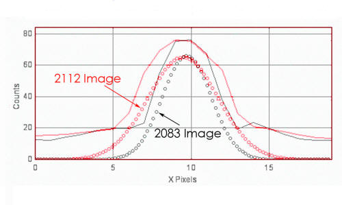 |
| Figure 9 - FWHM of the center star as the corner star moves into focus |
Fig. 9 is a cross sectional histogram of the Fig. 8 center star.
The black curve is a histogram of the 2083 center star and the red curve is the 2112 center star histogram. The FWHM for the 2083 star is 3.70 and the FWHM for the 2112 star is 5.26. The profiles curves show that image 2112 center is slightly out of focus with respect to image 2083 center - bad news!
The conclusion must be that it is not possible to find a position for the CCD where all stars are in focus with this telescope and field flattener/reducer. The CFZ for this lens and flattener configuration is not deep and/or wide enough for the CCD.
This set of histogram curves was generated by ImageJ (http://rsbweb.nih.gov/ij/features.html) and an FWHM plug-in, both suggested to me by Craig Stark of Stark Labs.
It is important to note that it is nearly impossible to make focuser adjustments of 20 microns or less (1/5 the thickness of 20lb paper), consistently, by hand. I now realize that focus at this level must be done with a stepper motor. These tests show the amazing consistency and precision of the Rigel Systems stepper motor system.
A
Conceptual Illustration Of A Fast Apo Field Curvature
Fig. 10
is a 2-D illustration of the focus zone of a fast apochromatic lens. The
blue area is the curved (partially flattened) focal critical focus zone
(CFZ) of the lens. The CCD sensors are on top of the red line. The CCD
will see a focused beam only in the area where the top of the red line
is inside the blue area. Areas of the CCD plane (the red line)
outside the blue zone are seen as out of focus by the CCD. In this
illustration the CCD image is focused in the center and out of focus at
the edges or corners of the image. The red line represents the 28 mm
diagonal of a Canon 20D CCD.
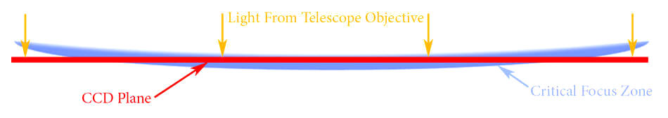
Figure 10 - A conceptual drawing of the
critical focus zone of a fast refractor

If we could curve the CCD in three dimensions to the curve of the blue CFZ area (as done in Schmidt cameras with film), the CCD image would always be in perfect focus.
Fig. 10 approximates the focus in figures 2 and 3 shown above. The center is excellent but the edges, or corners, are out of focus.
If we move the CCD plane higher, toward the telescope lens, the edges will be in better focus but the center of the beam will move out of focus. The images in Fig. 8 above shows what happens as the CCD is raised or moved closer to the objective. The edges improve but the center stars move out of the CFZ and slightly out of focus.
This drawing is not to scale. In this illustration, the CFZ is about 5 mm in depth. If the illustration were to scale, the blue zone would be 1000 cm (33 feet) wide!
An
Interesting Change To The Tele Vue Flattener/Reducer – An Improvement!
After running this set of tests, I decided to reduce the space between the TV flange and the CCD. I bought a thinner “T” adapter and lapped the face of the adapter on a precision machined steel surface. Tele Vue specifies that the distance between the TV .85X flange and the CCD plane should be 56 mm +/- 2 mm. All of the measurements made above were at the 56 mm spacing. Because my scope is 650 mm, I tried a 52 mm separation between the TV flange and the CCD plane. That is 4 mm less than the TV spec.
The result of the 52mm separation was improved corner focus with the 105/650 APM scope. After I made this improvement, I ran new and very detailed focus tests.
A new set of image tests
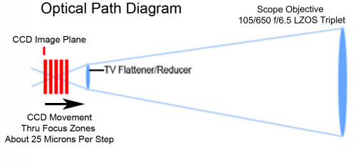 |
| Figure 11 - The optical path and CCD position for this test |
Fig.
11 is a representation of the optical
path for my tests. I made a quick analysis of 80 of the 120 images I
took. Each image was 30 seconds at ISO 1600.
In this focus analysis, I used
star FWHM to measure star focus changes. In this test sequence, the CCD
was shifted 25 microns per image toward the objective through the focus
zones of the CCD.
I picked four of the larger stars in the image that fell on a diagonal from the center to the corner of the image. I measured the FWHM of each of the four stars at 80 different positions of the CCD as it moved into focus and out.
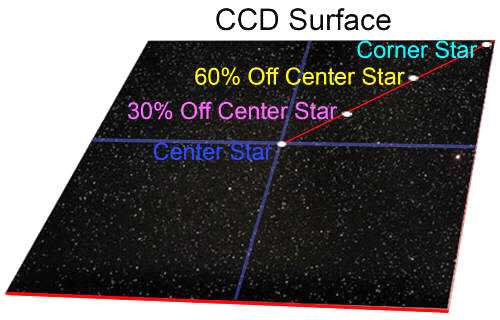 |
| Figure 12 - The selected stars for the CFZ chart analysis below |
Fig. 13 is a plot
of the FWHM values of each of the four stars as the CCD moved into good
focus and out the other side. This chart shows the changing focus zone
as the CCD moves toward the objective. Each of the four selected star
focus zones shown occurs at a different focuser position and each seems
to be about 125 to 200 microns deep. As the four stars come into focus,
the CFZ is shifting from the center to the corner of the CCD.
The CFZ depths are in approximate agreement with the simple CFZ equation for a105 mm, f/5.3 lens at beam centerline.
The focus difference between the center star focus (blue line) and the corner star (cyan line) focus is about 150 microns. Said differently – if the center stars are in focus, the corner stars are distorted.
The red arrows point to
minimum FWHM values which is interpreted to be best focus.
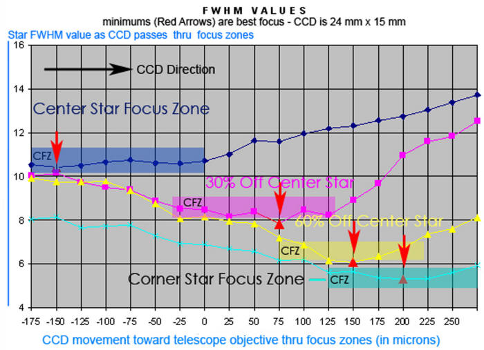
Figure 13 -
The Changing CFZ as the CCD is moved toward the objective 25
microns per image
If the
corner stars are in focus (not distorted), the center stars are slightly
out of focus. Most stars in the image are within 75 microns (or 5 % in
size) of perfect focus.
Chart notes: The
yellow FWHM value set on the chart was shifted slightly with a
multiplier to separate the data sets for clarity. The center star did
saturate and saturation could affect the FWHM and cause broadening of
the focus zone.
Chart Interpretation
The CFZ is still curved – even
with a flattener. This is a reality of modern astrophotography. A
remnant curvature after flattening is usually caused by a poor flattener
design or a flattener out of spec, or both. In this test, the incomplete
field flattening is caused by a flattener that is out of range for the
650 mm lens. It means that the “CFZ” will go to zero as the distance
from beam centerline increases on the CCD surface. Focus in wide field
astrophotography with an unflattened or semi-flattened field becomes a
compromise for the photographer where the photographer must pick a focus
point for best overall focus.
In a mathematical sense
-
The CFZ depth, for of a typical, non-flattened or semi-flattened fast
apochromatic lens, depends on both the f-speed of the lens, and the
distance from the beam centerline.
The Compromise!
 |
| Figure 14 - A full frame image |
Fig. 14 is an updated photo using the 52mm separation between the TV reducer/flattener flange and the CCD plane of the Canon 20D. This is a full frame image with minimum development.
 |
| Figure 15 - The upper right corner in detail |
Fig. 15 is a 580 x 440 upper right corner of full frame image in at 100%. This is the same area and magnification as shown in the earlier examples of focus such as Fig. 5.
This
focus is excellent. This is a color image - notice the lack of false
color even in the extreme corner! The LZOS triplet lenses are amazing!
It is also important to say that the new 52 mm spacing may not be
perfect. I do not know if 51mm or even 50 mm would work better. I would
need to have a professional machinist take 2 mm off the adapter to see
if the CFZ continues to improve.
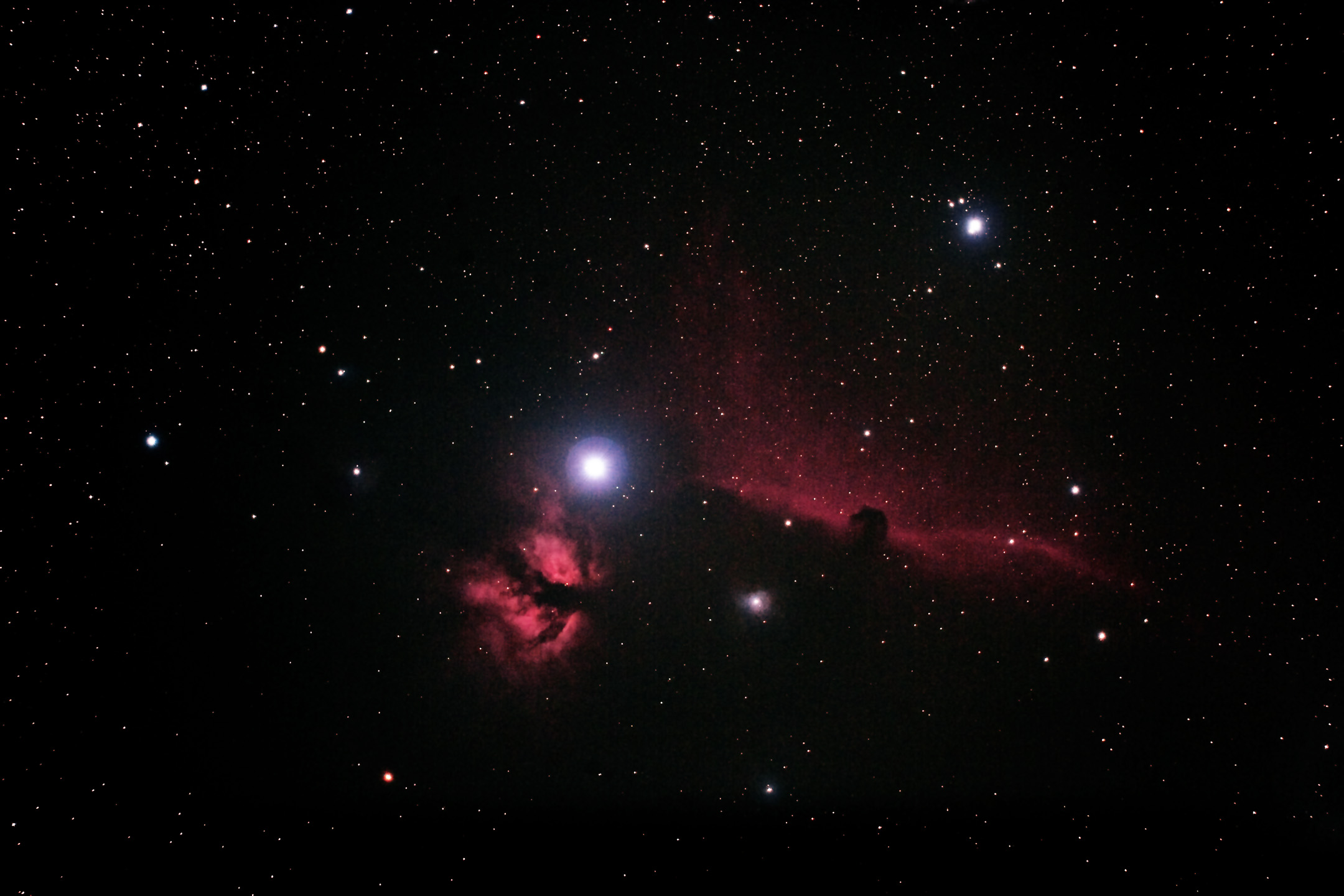
Finally – A
Real Astrophoto
And for those of you who would like to see an example of this focus in a real astrophoto here is a very quick image of Orion. This image is a composite of four, 2 minute exposures, at ISO 800, registered in DeepSkyStacker, and added in Photoshop. The image is full frame. Please understand that this is no contest winning view of Orion. It is simply a quick example of the best focus possible with the optics tested.
I have recently taken a series of photos using the TS Optics flattener available through APM and others. This is the flattener recommended by APM for the105/650 scope. The early results are excellent. And example of the 105/650 lens/flattener focus is below in a full frame image of M13. I used the GoldFocus 2.0 mask system to focus for this image. The GoldFocus mask and software has proven to be as accurate as my adjusting the CCD one 10 micron step at a time. This image has been reduced in size to 950 x 630 for this website but is still full frame. If you would like to see the full 3072 x 2048 original image, it can be seen here: www.steveluce.com/M13.htm in the second image down on the page.
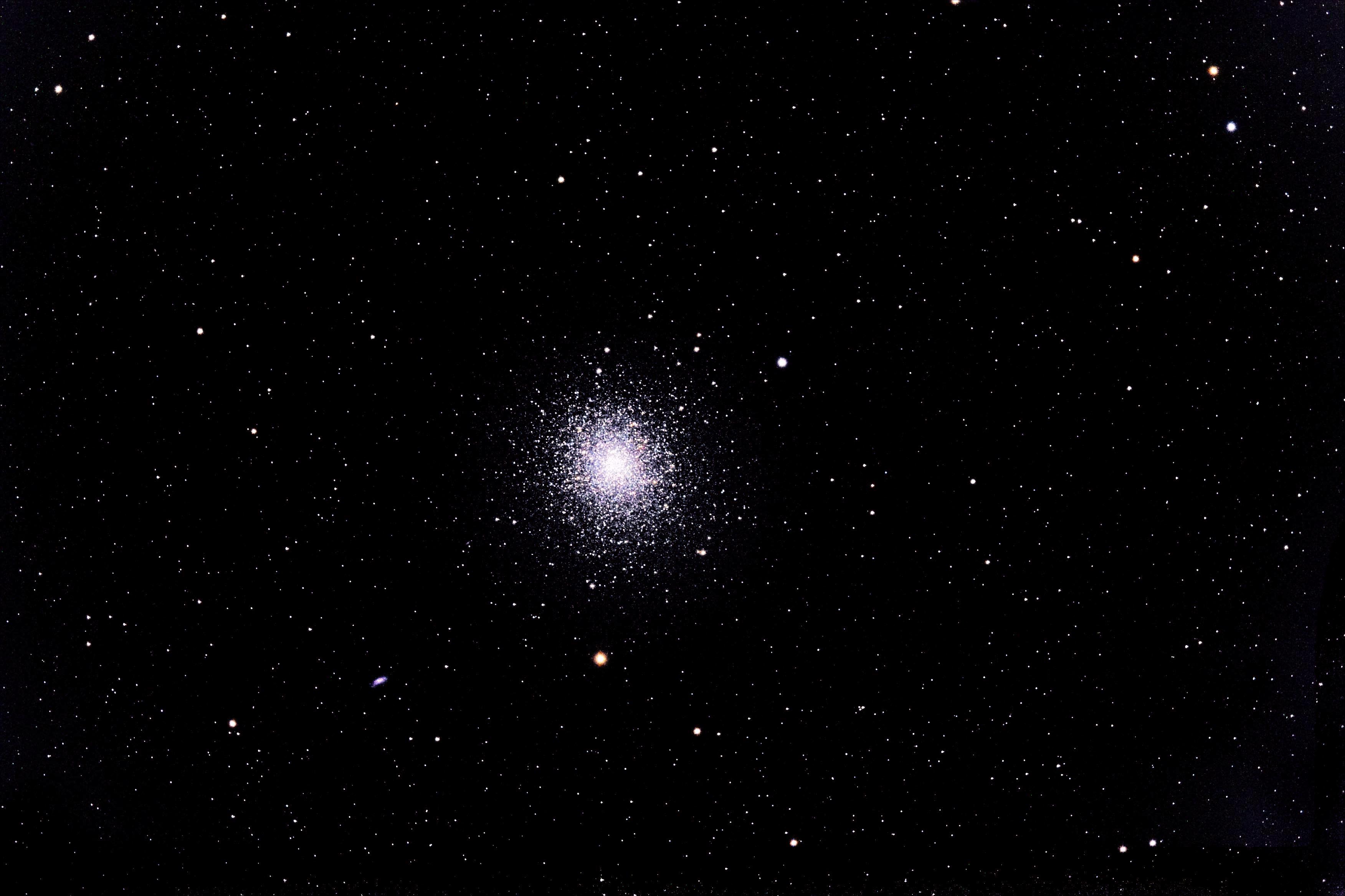
The CFZ with the TS Optics seems to be quite a bit deeper than the TV flattener/reducer lens used in the earlier tests above. I had no problem finding a focal point with all stars in focus – center and corner. But remember that the TS Optics lens does not reduce the focal length or increase the f-speed.
Throughout these tests, I have found the APM scope
to be of supreme quality both optically and mechanically. There is no
false color and the collimation is the best I have ever seen. It is
truly collimated for photography when most mid range scopes are simply
collimated for viewing.
GoldFocus
2.0
I also used the GoldFocus 2.0 focusing mask and software for this last test to find initial focus settings. The GoldFocus process is much easier and faster than any method I have used to date. I am extremely impressed with the GoldFocus mask and software system. One advantage of the system is that it will tell you (by voice) which way to move the focuser and by how much! It has become a standard tool in my focus studies and my astrophotography. The results appear to be equivalent to my most detailed focus processes especially when combined with a stepper motor focus system to be equivalent to my most detailed focus processes especially when combined with a stepper motor focus system. The image above of M13 was made with the help of GoldFocus.
Summary
Focus of a modern high quality fast apochromatic lens is a precision process. It requires tools such as the Rigel Systems stepper motor focus system and a focus interpreter such as the GoldFocus system. But the photographic results are amazing and well worth the effort. I have never seen such pinpoint stars as I have gotten with the APM 105/650 LZOS scope and a good flattener.
From this article, I am hoping to encourage the development of an auto-focus system that will produce a true 2-D and 3-D CFZ visualization. This process would use medical CT data slice methods as I have done for this article, manually. This would not be a simple, single plane, field curvature drawing based on a single image. This program would turn the stepper motor focuser and CCD into a CT scanner for a few minutes. The program would take 20 or 30 images and produce 3-D CFZ views and then place the CCD for optimum focus. The result would be a display that would be a perspective view of the CFZ with the CCD placed precisely in the CFZ.
Steve Luce